Aether-in-a-Box with External 4G Radio
This document describes how to set up an Aether-in-a-Box (AiaB) with a Sercomm eNodeB and connect real devices (e.g., 4G phones). It assumes that you are already familiar with running AiaB with emulated eNodeB/UE. AiaB on Hardware Radios is suitable for laboratory experiments and proof-of-concept deployments. Its goals are to demonstrate how to configure a real eNodeB to work with Aether, and to provide an easy-to-install environment where Aether’s features can be explored with real devices. To create this setup you will need the following equipment:
Server for running AiaB (SD-CORE / UPF / ROC)
Ubuntu 18.04 or 20.04 clean install
Haswell CPU family or newer
At least 4 CPUs and 12GB RAM
Internet connection
Ability to run “sudo” without a password
No firewall running on the AiaB host
4G small cell eNodeB
Example: Sercomm CBRS LTE small cell eNodeB
SIM card writer and blank SIM cards
IMPORTANT: AiaB is for simple deployment scenarios and so makes some simplifying assumptions:
AiaB assumes 4G SD-CORE is deployed. Running both 4G and 5G SD-CORE simultaneously in AiaB is currently not supported. However, running both 4G and 5G SD-CORE simultaneously is supported by Aether.
Performance and scalability are not goals. AiaB does not support I/O acceleration (e.g., with SR-IOV). However, performance and scalability are goals of the Aether project.
AiaB assumes that the server and the eNodeB are connected to the same LAN and share the same IP subnet; in other words they can reach each other in a single hop and there is no IP router between them. This simplifies communication between the eNodeB and the UPF, which is running inside a container and has a private IP address that is not necessarily routable on the local network. However, this is not a requirement for all Aether deployments.
AiaB also assumes that the AiaB server’s network is configured using systemd-networkd, which is the default for Ubuntu, and copies some files into /etc/systemd/network; the reason for this is to enable persistence of AiaB’s networking configuration across server reboots. This configuration method is specific to AiaB.
Preparation
Create SIM cards by following the instructions for your SIM card writer. Of course you are free to use any values for IMSI, etc. that you choose, but these are the values that will work with the rest of the configuration in this document:
IMSI: each one is unique, matching pattern
315010*********(15 digits)OPc:
69d5c2eb2e2e624750541d3bbc692ba5Transport Key:
000102030405060708090a0b0c0d0e0f
If you choose different values for your SIM cards, you will need to modify subsequent configuration steps appropriately.
Insert the SIM cards in devices that you wish to be able to connect to the Aether network.
Server setup
The server will run Aether-in-a-Box. The eNodeB will connect to the server over the local network. Perform these steps to prepare the server for the AiaB install:
Connect the server to the local network
Perform a clean install of Ubuntu 18.04 or Ubuntu 20.04 on the server
Verify that systemd-networkd is being used to configure networking (e.g., run
systemctl status systemd-networkd.service)Set up password-less sudo for the user that will install Aether-in-a-Box
After the steps above have been completed, install Aether-in-a-Box as follows:
sudo apt install git make
git clone "https://gerrit.opencord.org/aether-in-a-box"
cd aether-in-a-box
Next, modify the file sd-core-4g-values.yaml. Under subscribers,
add an IMSI range for the SIM cards you created, with the Transport Key
and OPc values you used earlier. For example, the following will add
IMSIs between 315010999912301 and 315010999912303:
subscribers:
- ueId-start: "315010999912301"
  ueId-end: "315010999912303"
  plmnId: "315010"
  opc: "69d5c2eb2e2e624750541d3bbc692ba5"
  key: "000102030405060708090a0b0c0d0e0f"
  sequenceNumber: 135
Determine which is the interface that has L3 connectivity to the
eNodeB – this will be DATA_IFACE in the configuration later. If
the eNodeB will also be connected to the local network, then this is just the
server’s primary interface. If the eNodeB will be connected via an
isolated L2/L3 network segment, then DATA_IFACE refers to the server
interface on that network. Remember this interface for later.
Option 1: Configure Aether with ROC
The Aether ROC provides a GUI and API for dynamically configuring Aether. If you don’t wish to use the ROC to configure AiaB, you can skip to the next section.
Note
Aether Monitoring is available only when Aether is deployed using ROC.
Install AiaB as follows (specifying DATA_IFACE from above):
ENABLE_OAISIM=false DATA_IFACE=<iface> CHARTS=latest make roc-4g-models 4g-core
Next, use the ROC to add information about your SIM cards. The ROC GUI is available at http://<server-ip>:31194.
Choose Configuration > Site from the drop-down at top right and edit
the AiaB site. Change the following values and click Update:
MCC: 315
MNC: 010
Choose Sim Cards from the drop-down at top right. Edit the
existing entries to reflect the SIM cards you are adding to devices
by replacing their IMSI values. Click Update after each edit.
If you want to connect more than two devices, consult the ROC
documentation.
Finally, click the Basket icon at top right and click the Commit button.
Now jump to the Verifying the AiaB installation section.
Option 2: Configure Aether without ROC
It is possible to configure Aether without the ROC, using static YAML files and the SimApp service. If you have already installed the ROC, you should skip this section.
Edit sd-core-4g-values.yaml. Change mcc and mnc as follows:
plmn:
  mcc: "315"
  mnc: "010"
Also add the IMSIs of your devices under imsis, for example:
device-groups:
- name:  "4g-oaisim-user"
  imsis:
    - "315010999912301"
    - "315010999912302"
    - "315010999912303"
Install AiaB as follows (specifying DATA_IFACE from above):
ENABLE_OAISIM=false DATA_IFACE=<iface> CHARTS=latest make 4g-core
Verifying the AiaB installation
Installing AiaB will take about 20 minutes with a fast Internet
connection. If you see any errors / timeouts, try running the make
command again. The build will finish with a message:
“Your MME IP address is… ” This is just the IP address assigned to
the DATA_IFACE. Remember this for the eNodeB setup.
When the install is complete, check that the 4G SD-CORE is running as follows:
$ kubectl -n omec get pod
NAME                     READY   STATUS    RESTARTS   AGE
cassandra-0              1/1     Running   0          7m27s
config4g-0               1/1     Running   0          7m27s
hss-0                    1/1     Running   0          7m27s
mme-0                    4/4     Running   0          7m27s
pcrf-0                   1/1     Running   0          7m27s
simapp-65dc44b9d-stx6q   1/1     Running   0          7m27s
spgwc-0                  2/2     Running   0          7m27s
upf-0                    5/5     Running   0          7m27s
You should see all pods in Running status.
If you have installed the ROC, check that all its pods are running as follows:
$ kubectl -n aether-roc get pod
NAME                                           READY   STATUS    RESTARTS   AGE
aether-roc-api-78cc548bb9-7vjs2                1/1     Running   0          4m16s
aether-roc-gui-v2-6d674fd446-tttb5             1/1     Running   0          4m16s
aether-roc-umbrella-grafana-74f8489c8f-s9p45   2/2     Running   0          4m16s
aether-roc-websocket-855d64549b-44fnc          1/1     Running   0          4m16s
onos-cli-5d448ff6c4-stq5t                      1/1     Running   0          4m16s
onos-config-7f4df96b88-vtp5s                   6/6     Running   0          4m16s
onos-consensus-store-0                         1/1     Running   0          4m15s
onos-topo-585c7c8976-6jq7b                     3/3     Running   0          4m16s
sdcore-adapter-v2-5646d455b9-2d6zl             1/1     Running   0          4m15s
You should see all pods in Running status.
The UPF pod connects to the DATA_IFACE specified above using macvlan networks called
core and access. Next, check that these have been successfully created, e.g. using
ifconfig:
$ ifconfig core
core: flags=4163<UP,BROADCAST,RUNNING,MULTICAST>  mtu 1500
    inet 192.168.250.1  netmask 255.255.255.0  broadcast 192.168.250.255
    ether 16:9d:c1:0f:19:3a  txqueuelen 1000  (Ethernet)
    RX packets 513797  bytes 48400525 (48.4 MB)
    RX errors 0  dropped 0  overruns 0  frame 0
    TX packets 102996  bytes 26530538 (26.5 MB)
    TX errors 0  dropped 0 overruns 0  carrier 0  collisions 0

$ ifconfig access
access: flags=4163<UP,BROADCAST,RUNNING,MULTICAST>  mtu 1500
    inet 192.168.252.1  netmask 255.255.255.0  broadcast 192.168.252.255
    ether 7a:9f:38:c0:18:15  txqueuelen 1000  (Ethernet)
    RX packets 558162  bytes 64064410 (64.0 MB)
    RX errors 0  dropped 0  overruns 0  frame 0
    TX packets 99553  bytes 16646682 (16.6 MB)
    TX errors 0  dropped 0 overruns 0  carrier 0  collisions 0
:: _understanding_aiab_networking
Understanding AiaB networking
Why does AiaB create the core and access interfaces? These are necessary to enable
the UPF to exchange packets with the eNodeB (access) and Internet (core); they correspond to
the last two network interfaces below inside the UPF’s bessd container:
$ kubectl -n omec exec -ti upf-0 bessd -- ip addr
1: lo: <LOOPBACK,UP,LOWER_UP> mtu 65536 qdisc noqueue state UNKNOWN group default qlen 1000
    link/loopback 00:00:00:00:00:00 brd 00:00:00:00:00:00
    inet 127.0.0.1/8 scope host lo
    valid_lft forever preferred_lft forever
    inet6 ::1/128 scope host
    valid_lft forever preferred_lft forever
3: eth0@if30: <BROADCAST,MULTICAST,UP,LOWER_UP> mtu 1450 qdisc noqueue state UP group default
    link/ether 8a:e2:64:10:4e:be brd ff:ff:ff:ff:ff:ff link-netnsid 0
    inet 192.168.84.19/32 scope global eth0
    valid_lft forever preferred_lft forever
    inet6 fe80::88e2:64ff:fe10:4ebe/64 scope link
    valid_lft forever preferred_lft forever
4: access@if2: <BROADCAST,MULTICAST,UP,LOWER_UP> mtu 1500 qdisc noqueue state UP group default
    link/ether 82:b4:ea:00:50:3e brd ff:ff:ff:ff:ff:ff link-netnsid 0
    inet 192.168.252.3/24 brd 192.168.252.255 scope global access
    valid_lft forever preferred_lft forever
    inet6 fe80::80b4:eaff:fe00:503e/64 scope link
    valid_lft forever preferred_lft forever
5: core@if2: <BROADCAST,MULTICAST,UP,LOWER_UP> mtu 1500 qdisc noqueue state UP group default
    link/ether 4e:ac:69:31:a3:88 brd ff:ff:ff:ff:ff:ff link-netnsid 0
    inet 192.168.250.3/24 brd 192.168.250.255 scope global core
    valid_lft forever preferred_lft forever
    inet6 fe80::4cac:69ff:fe31:a388/64 scope link
    valid_lft forever preferred_lft forever
In other words, there are interfaces named access and core both inside and outside the UPF. All four
are MACVLAN interfaces
bridged with DATA_IFACE. There are two subnets on this bridge: the two access interfaces are on 192.168.252.0/24
and the two core interfaces are on 192.168.250.0/24. It is helpful to think of two links, called
access and core, connecting the AiaB host and UPF. AiaB sets up IP routes on the AiaB host and inside the UPF
to forward packets into and out of the UPF as explained below.
The access interface inside the UPF has an IP address of 192.168.252.3; this is the destination IP address
of GTP-encapsulated data plane packets from the eNodeB. In order for these packets to actually find their way
to the UPF, they must arrive on the DATA_IFACE interface and then be forwarded on the access interface
outside the UPF.
The next section describes how to configure a static route on the eNodeB in order to send the GTP packets to
DATA_IFACE. Forwarding the packets to the access interface is done by the following kernel route on the
AiaB host (which should be present if your AiaB installation was successful):
$ route -n | grep "Iface\|access"
Destination     Gateway         Genmask         Flags Metric Ref    Use Iface
192.168.252.0   0.0.0.0         255.255.255.0   U     0      0        0 access
The high-level behavior of the UPF is to forward packets between its access to core interfaces, while
at the same time removing/adding GTP encapsulation on the access side. Upstream packets
arriving on the access side from a UE have their GTP headers removed and the raw IP packets are
forwarded to the core interface. The routes inside the UPF’s bessd container will look something
like this:
$ kubectl -n omec exec -ti upf-0 -c bessd -- ip route
default via 169.254.1.1 dev eth0
default via 192.168.250.1 dev core metric 110
128.105.144.0/22 via 192.168.252.1 dev access
128.105.145.141 via 169.254.1.1 dev eth0
169.254.1.1 dev eth0 scope link
192.168.250.0/24 dev core proto kernel scope link src 192.168.250.3
192.168.252.0/24 dev access proto kernel scope link src 192.168.252.3
The default route via 192.168.250.1 is directing upstream packets to the Internet via the core interface,
with a next hop of the core interface outside the UPF.
These packets undergo source NAT in the kernel (also configured by AiaB) and are sent to the IP destination
in the packet. The return (downstream) packets undergo reverse NAT and now have a destination IP address of the UE.
They are forwarded by the kernel to the core interface by these rules on the AiaB host:
$ route -n | grep "Iface\|core"
Destination     Gateway         Genmask         Flags Metric Ref    Use Iface
172.250.0.0     192.168.250.3   255.255.0.0     UG    0      0        0 core
192.168.250.0   0.0.0.0         255.255.255.0   U     0      0        0 core
The first rule above matches packets to the UEs (on 172.250.0.0/16 subnet). The next hop for these
packets is the core IP address inside the UPF. The second rule says that next hop address is
reachable on the core interface outside the UPF. As a result the downstream packets arrive in the
UPF where they
are GTP-encapsulated with the IP address of the eNodeB. Inside the UPF these packets will match a route
like this one (see above; 128.105.144.0/22 in this case is the DATA_IFACE subnet):
128.105.144.0/22 via 192.168.252.1 dev access
These packets are forwarded to the access interface outside the UPF and out DATA_IFACE to the eNodeB.
Recall that AiaB assumes that the eNodeB is on the same subnet as DATA_IFACE, so in this case it also has an
IP address in the 128.105.144.0/22 range.
Manual Sercomm eNodeB setup
The instructions in this section describe a basic configuration of the eNodeB. For a more comprehensive guide to eNodeB configuration see eNB Installation.
The Sercomm eNodeB has two Ethernet ports: WAN and LAN. We will use the LAN port for configuration of the eNodeB and the WAN port for normal operation. Connect the eNodeB WAN port to the local network.
Connect the eNodeB LAN port to a free Ethernet port on a Linux machine
(say, a laptop) that will be used for the initial configuration of
the eNodeB. On that machine run dhclient on the interface corresponding
to the Ethernet port, for example:
sudo dhclient eth1
The interface should receive an IP address from the Sercomm eNodeB on
the 11.11.11.0/24 subnet. Check this using ifconfig:
$ ifconfig eth1
eth1: flags=4163<UP,BROADCAST,RUNNING,MULTICAST>  mtu 1500
    inet 11.11.11.100  netmask 255.255.255.0  broadcast 11.11.11.255
    inet6 fe80::2e0:4cff:fe68:2f76  prefixlen 64  scopeid 0x20<link>
    ether 00:e0:4c:68:2f:76  txqueuelen 1000  (Ethernet)
    RX packets 264652  bytes 216094312 (216.0 MB)
    RX errors 0  dropped 0  overruns 0  frame 0
    TX packets 183978  bytes 36528580 (36.5 MB)
    TX errors 0  dropped 0 overruns 0  carrier 0  collisions 0
The eNodeB IP address should be 11.11.11.188 on that link. Verify this using ping:
$ ping 11.11.11.188
To access the Sercomm eNodeB admin page, you can run a Web browser on
the laptop and direct it to https://11.11.11.188. Login to the admin
interface as user: sc_femto and password: scHt3pp.
Click the NetWork set menu at the top. In the first section
IP Address, set Connect type: DHCP (assuming this is supported on
your local network, otherwise set up a static IP address).
Click the blue Save button at the bottom.
Next, click the Manage menu at the top and then click the
LTE Basic Setting tab. Change these parameters and click Save:
Carrier Number: 2
Carrier Aggregation: Unset
BandWidth: 20
FrequencyBand: 48,48
EARFCN: 55440,55640
CellIdentity: 2,1
PCI: 100,101
TxPower: 20
Tunnel Type: IPv4
MME IP Address: <MME IP address from AiaB installation>
PLMNID: 315010
TAC: 1
Sync Source: FREE_RUNNING
Enable CWMP: Unset
Click the SAS Configuration tab. In the Location Configuration
section, enter these values and click “Save”:
Location: Indoor
Location Source: Manual
Latitude: 0
Longitude: 0
Elevation: -18000
Next we need to add a static route to the UPF address, 192.168.252.3,
on the eNodeB. Click on TR098 menu and then click on IP tab.
Scroll down to Device.Routing.Router. section. Click View List.
Add this info on the blank line:
Enable: Set
StaticRoute: Set
DestIPAddress: 192.168.252.0
DestSubnetMask: 255.255.255.0
GatewayIPAddress: <Use MME IP address from AiaB installation>
Interface: Device.IP.Interface.1.
Then click the Add button at the far right.
Finally click the FAPService menu and then go to the FAPControl
tab. Check the box next to AdminState in the first section and
click Save.
After these changes are made, reboot the eNodeB by clicking the red
power button square at top right and selecting Reboot. When the
eNodeB comes back up, it should have an IP address on the network
(via the WAN port), and the admin page should now be available on
https://<endoeb-ip>.
Test connectivity from the eNodeB to the MME and the UPF running on
the server as follows. Login to the eNodeB admin interface, click
the “Manage” menu at the top, and click the IP Diagnose tab. Under
Ping and Traceroute, select ping, and then type the following IP
addresses into the box to the right and click Run:
<MME IP address from AiaB installation>
192.168.251.1
192.168.252.3
If all of these are working, then you are ready to try to connect devices to the network.
Automated Sercomm eNodeB Setup (experimental)
The eNodeB service is used to provide the automatic configuration of the eNodeB device. It can be installed by the following command:
make enodebd
The eNodeBD service will listen on port 31005 and you need to configure the management url of eNodeB device
to make eNodeB connect to the eNodeBD service.
By default, the eNodeBD service will configure the eNodeB with the pre-defined configuration, but you can also add
the customized configuration per serial number in the magma_config/serial_number/ directory. For the example
configuration, please duplicate acs_common.yaml and rename it as the {serial_number}.yaml.
The automated setup via eNodeBD won’t configure the static route to UPF service, please follow the UPF route setup step describes in Manual Sercomm eNodeB setup to add the static route.
Configuration and Validation
To configure the Sercomm eNodeB be managed by eNodeBD service, access the TR098 configuration page:
https://<enodeb_ip_address>/TR098_DevFeature.htm
The configuring path is: TR098 > MgmtServer > Device.ManagementServer.URL
Check the EnableCWMP option to enable the management function.
Fill the eNodeBD URL into Device.ManagementServer.URL field.
After you fill in the AiaB IP with eNodeBD service port as URL into the field, you need to restart the device. And you will be able to see the eNodeBD log by the following command (the pod name may be different):
kubectl -n aether-apps logs aether-enodebd-b46897745-fj5qj -f
Also, you can install the monitoring dashboard to view the eNodeB status on Grafana.
Connecting Devices
Documenting how to configure different types of devices to work with Aether is work-in-progress, but here are some basic guidelines.
The values of IMSI, OPc, and Transport Key you have configured on your SIM cards
must be entered into the subscribers block under omec-sub-provision in the
sd-core-4g-values.yaml file. If you are not using the ROC, the IMSIs must also be
added under device-groups, and the relevant device group added under network-slices.
If you are using the ROC, then your devices must be configured there and the associated
device group added to a slice. In either case it is necessary to configure the basic info
under subscribers.
Be aware that not all phones support the CBRS frequency bands. AiaB is known to work with recent iPhones (11 and greater) and Google Pixel phones (4 and up). CBRS may also be supported by recent phones from Samsung, LG Electronics and Motorola Mobility, but these have not been tested with AiaB. If you successfully test a phone on AiaB, please post details on Slack so we can add it to the list.
The APN to configure on your phone is internet.
Enable Monitoring
To easily monitor your AiaB deployment, you can run the following command to deploy the Prometheus/Grafana monitoring stack on your AiaB server:
make monitoring-4g
After this step, Grafana is available at http://<server-ip>:30950. You will see a number of system dashboards for monitoring Kubernetes, as well as a simple AiaB dashboard that enables inspection of the local Aether state.
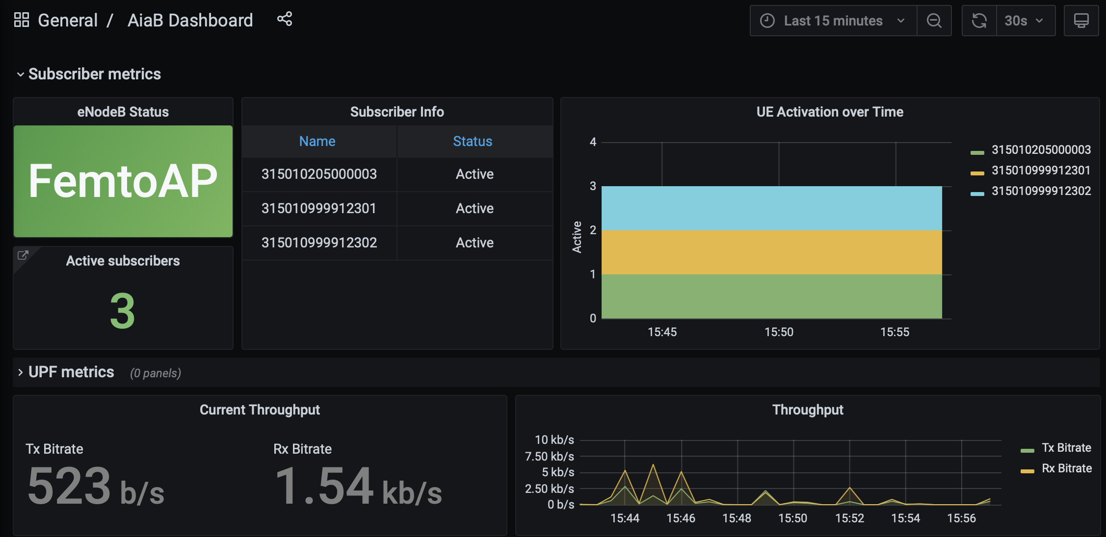
Figure 4. 4G Grafana AiaB Dashboard
The dashboard shows whether the eNodeB is connected to the core, how many active UEs there are, and the uplink (Tx Bitrate) and downlink (Rx Bitrate) throughput at the UPF.
To create a new dashboard for Aether, you can login to Grafana as user admin with password prom-operator. You can also modify an existing dashboard by making a copy of the dashboard and editing that. Note that any dashboard changes will be lost if Grafana is restarted; if you want to make your dashboard more permanent, you can save its JSON to a file, add the file to directory aether-in-a-box/resources/4g-monitoring, and edit kustomization.yaml in that directory to add the file to the ConfigMapGenerator block. After these steps, re-running make monitoring-4g should install the dashboard in a ConfigMap and Grafana should automatically load it.
Troubleshooting
Please refer Aether Troubleshooting Guide